Aligning the OPTEX SL beams
OPTEX Smart Line active infrared beams come in pairs and operate by sending a continuous signal from a transmitter beam to a receiver beam. An alarm would be triggered if the signal is interrupted. A good alignment of the two beams is essential to enable a strong signal and avoid any possible interferences.
In this tech tip we review the alignment process for:
- SL-QNR, SL-QDP, SL-QDM series, wired quad beams set with a detection range from 60 to 200m depending on the model
- SL-QNR and SL-QFR, wireless quad beams set with a detection range of 60 up to 100m depending on the model
Before starting the alignment process, be sure that both SL transmitter and receiver are in their final positions and fixed firmly in place. Once in place, the alignment process can start and can be done in two steps.
Step one: Visual alignment
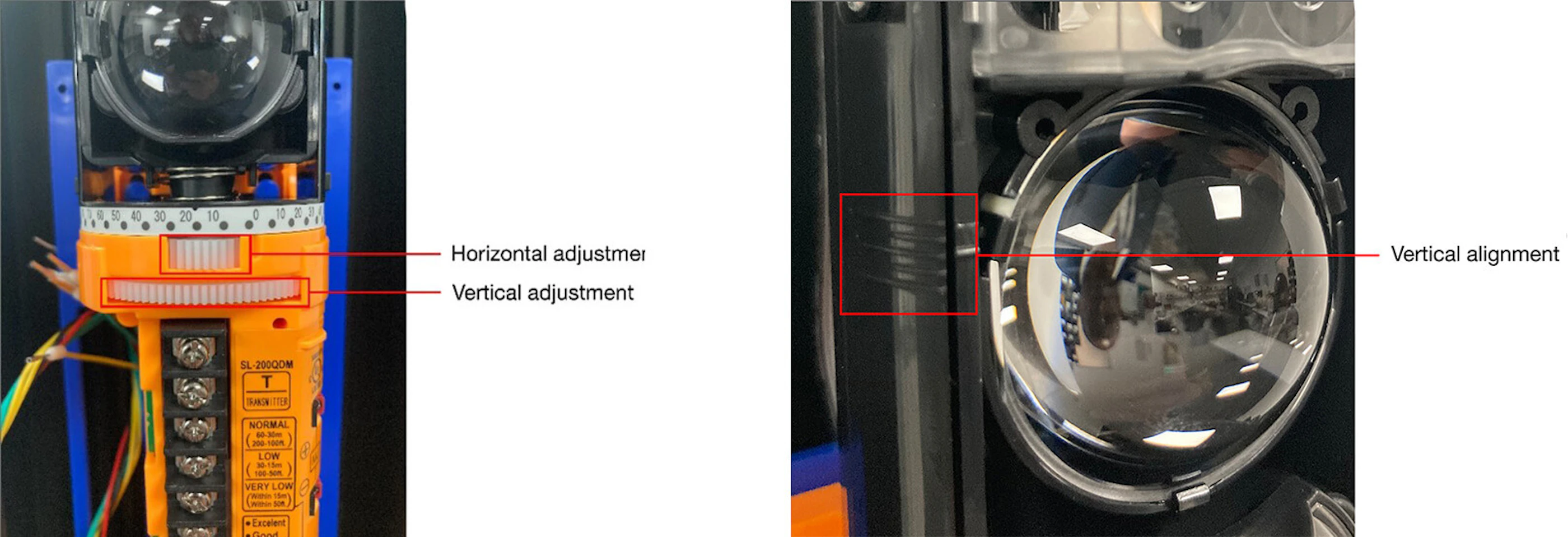
The solution for vertical adjustment is similar. Marks are located on the side of the black bracket where lenses are placed. Make sure the upper and bottom set of the lenses are on the same angle to avoid the situation where one of them is on the line of sight but another is on a different angle and the beam reflects from the wall or another surface.

Step two: Fine tuning the alignment with a voltmeter
These are supplied inside the beam cover, or if using beam towers they will be provided in the box (do not throw these away). Detach the blocking plate from each beam cover and first use it to block the lower or upper beam lens.
Save the blocking plates for future use by hooking them on the screw inside the cover.

Once blocking plates are in place connect your voltmeter to the monitor jack on the receiver beam and begin adjusting until the multi meter voltage reading is over 2V ( for SL-QDP/QDM units) or over 3.5-5V ( for SL-QN units). Continue until the reading reaches its optimum. This process should be repeated on the set of beams (either top or bottom) you have not adjusted. The optimum voltage can be found inside the beam cover.
Remember to place the blocking plates on both the transmitter and receiver. If you place it only on the receiver it will receive the lightbeam from two sets of transmitter lenses and it can malfunction due to a higher than recommended voltage.
Monitor Jack Output (v) |
Alignment Level |
2.0V or over |
Excellent |
1.5V or over |
Good |
1.2V or over |
Fair |
Under 1.2V |
Realign |
Important information to perform and validate the alignment.
- If the beams are operating next to a shiny wall or surface, reduce the reflection of the beam on the surface by starting the alignment of the transmitter angled away from the surface and adjusting it until the receiver can see the beam (do not angle towards the surface).
- Perform the walk test in three different points at least – in front of the transmitter, in front of the receiver and half way between them. It is always better to cross the line in many points, especially if the installation is done in a location where there is a chance of reflections.

